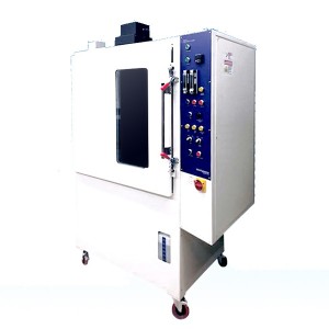
Flame Spread Tester
Thermal and Acoustic Insulation Flame Spread Tester for Detecting Thermal Insulation
Product Profile of the Contact Heat Transimmision Test Apparatus
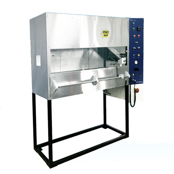
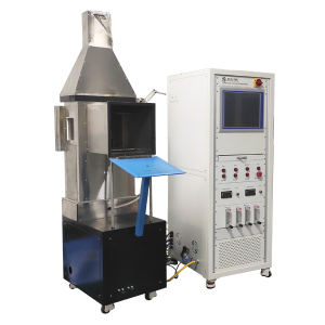
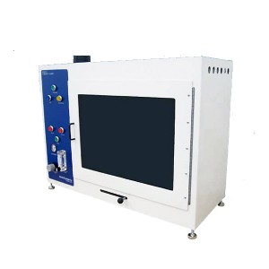
FAA-approved flame spread tester for thermal insulation materials is used to detect the critical thermal radiation flux of materials after exposure to standard thermal radiation sources. The flame spread tester for heat and sound insulation materials can meet international standards such as FAR Part 25 Appendix F Part Vl, Airbus AITM 2.0053, Boeing BSS 7365, and civil aviation MH/T6042-2006.
Performance Characteristics of the Contact Heat Transimmision Test Apparatus
1. The radiation plate test box is a closed equipment, which includes built-in chimney and other components.
2. Radiant heat source is 400 VAC 3-phase electric heating plate, PID temperature control mode, temperature control accuracy is 0.1 degree.
3. The radiation heat source is installed in the frame. There are six 76mm wide radiation strips on the electric heating plate. The radiation strips are perpendicular to the long side of the electric heating plate and can withstand operating temperature not less than 704 degrees.
4. The radiation plate should be placed in the test box at an angle of 30 degrees from the horizontal plane of the sample.
5. Equipped with pneumatic sliding drawer, users can realize automatic control of sample entry and exit.
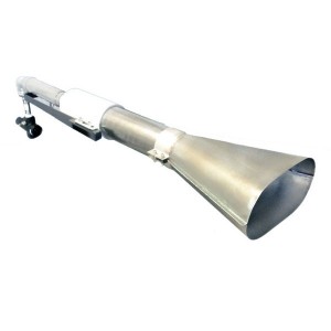
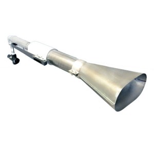
6. The burner is an axisymmetric propane ignition device with an aperture of 0.15mm.
7. The burner moving device can make the flame level at least 51 mm higher than the sample plane.
8. A laser pointer is equipped to accurately measure the flame propagation, which is used to monitor the flame spread distance.
9. A thermocouple can be inserted on the back of the box. The thermocouple is 279 mm from the back wall of the box and 292 mm from the right side of the box wall. It is located 51 mm below the radiation plate. The temperature accuracy of the thermocouple is 2 degrees.
10. Water-cooled heat flow meter, the range of heat radiation flux is not less than 60KW/m2, equipped with self-circulating cooling water source.
11. The heat flow meter bracket is made of 3.2mm thick steel plate. The bracket accommodates the refractory plate.
12. The heat flow meter bracket has three 25.4 mm diameter jacks passing through the supporting plate. The distance between the center of the first jack and the surface of the heat radiation plate is 191+3 mm, and the distance between the two adjacent jacks should be 51 mm.
13. Equipped with two kinds of sample clamps, two sample brackets, one is standard type and the other is short for hook-and-loop test.
14. Equipped with data acquisition system, computer and printer device 1.
15. The test time is automatically recorded and stopped. The precision of time control is 0.1s (seconds).
Product Parameters of the Contact Heat Transimmision Test Apparatus
| Electricity requirements | 220 V, 35 Amps |
| Weight | 185KG |
| Size | 1900mm (W) x 1750mm x (H) x 750mm (D) |
| Standard | AITM 2.0053、BSS 7365、FAR PART 25 APPENDIX F Part VI |
| Ambient temperature | 10 ℃ to 35 ℃ |
| Auxiliary Gas | Air Compressor Gas |
| Combustion gas | propane |

