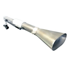
Fuel Testing System
Fuel Testing System for Aviation Power Parts Different Test Standards can be Met
Product Profile of Fuel Testing System for Aviation Power Parts
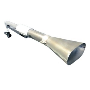
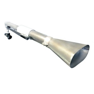
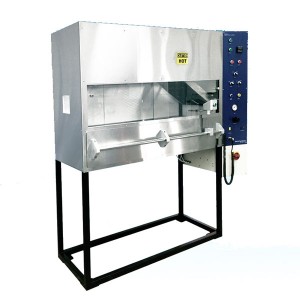
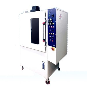
The NexGen aviation fuel burner approved by FAA of the Federal Aviation Administration of the United States can be used for fuel combustion testing of many aviation materials. As the Park DPL 3400, Lennox Model OB-32 and Carlin Model 200 CRD previously recognized by FAA have all been discontinued, FAA has developed the NexGen burner for the next generation of aviation fuel burners. NexGen combustor adopts the operation principle of the previous generation combustor, and can accurately measure the test parameters of the input gas and fuel. At the same time, the instrument can facilitate the future upgrade of FAA.
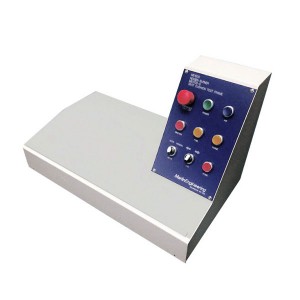
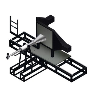
The fuel combustion test of Aeronautical power components can be completed automatically by configuring the test frame of Aeronautical power components and the power loading system.
Performance characteristics
1. The conical cylinder of burner is made of corrosion resistant and high temperature resistant alloy.
2. NexGen aviation fuel burner includes spoiler, fuel nozzle, igniter, fuel rail, fixer, ventilation tube and shell, muffler, acoustic resistance and other components.
3. Equipped with fuel pressure gauge, fuel solenoid valve, fuel temperature detection device, air pressure regulating valve, air temperature detection device;
4. Equipped with a gas and air temperature control device ice bath with a volume not less than 2 x 0.14 m3, the fuel temperature can be controlled.
5. By changing fuel nozzle and air pressure input, different test standards can be met.
6. The burner covers the fuel pipeline and fuselage with insulation blanket.
7. Module unit of NexGen burner support system;
8. Heavy-duty steel frame, which can install test samples horizontally and vertically.
9.Seven ceramic-encapsulated, metal sheaths and grounded K-type (nickel-chromium-nickel-aluminium) thermocouples with a diameter of 1.6 mm should be used for calibration. Their conductors should have an external diameter of 0.254 mm, a cross-sectional area of 0.0507 mm2 and a resistance of 361_/km (American wire gauge 30 AWG). The thermocouple should be fixed on an angle steel bracket to form a thermocouple comb so that it can be placed on the sample bracket during calibration.
10. The heat radiation flux sensor is equipped with a cooling device and installed on a fixed support.
Product parameters
| Dimensions | 1500 mm (W) x 1800 mm (H) x 900 mm |
| Weight | 150 KG |
| Electricity requirements | 220V, 10A |
| Ambient temperature | 10 ℃ to 35 ℃ |
| Fuel requirements | aviation kerosene |
| Gas requirements | no less than 120 PSI air compressor |
| Application area | Aviation Materials |
| Standard | FIRE TEST HANDBOOK: Chapter 12 |


